


The Extreme Networks ACC-BKT-AX-WP-SPARE mounting bracket is a replacement and spare wallplate solution for Extreme Networks wireless access points. Designed for wall, solid ceiling, and junction box installations, this stainless-steel bracket allows installers to replace lost or damaged in-box hardware while maintaining consistent, secure access point mounting.
Key Features of Extreme Networks ACC-BKT-AX-WP-SPARE Mounting Bracket
Spare stainless-steel wallplate mounting bracket for Extreme Networks access points
Suitable for wall, solid ceiling, and junction box installations
Identical to the in-box wallplate supplied with supported access points
Includes full hardware kit for secure installation
Sold separately as a replacement or additional bracket
Replacement Wallplate Mounting Solution
The ACC-BKT-AX-WP-SPARE is intended as a direct replacement for the standard in-box wallplate mounting bracket. It is ideal when an original bracket is lost, damaged, or when additional brackets are required for spare stock or staged deployments.
Supports Multiple Installation Scenarios
This spare bracket supports wall mounting, solid ceiling installations, and junction box mounting, offering flexibility across a wide range of indoor deployment environments.
Stainless-Steel Construction
Manufactured from durable stainless steel, the wallplate bracket provides a strong, reliable mounting surface that helps ensure long-term stability and secure access point placement.
Complete Hardware Kit Included
The SPARE accessory includes a clear hardware bag containing all required fasteners, including a T8 security Torx locking screw, Phillips screws for USA junction box attachment, pan-head screws for wall mounting, and plastic screw-in anchors.
Ideal for Maintenance and Spares
By keeping ACC-BKT-AX-WP-SPARE brackets on hand, organisations and installers can minimise downtime, simplify maintenance, and ensure consistent mounting standards across wireless deployments.
The ACC-BKT-AX-WP-EXT accessory, also called the wall extension accessory is used with the wall plate in-box stainless-steel bracket for EU model junction box installations. The -EXT accessory must be purchased separately.
The EXT accessory bag contains the following items:
One ACC-BKT-AX-WP-EXT accessory
Four Phillips washer pan head M2.5×7 mm long screws to attach the extension to the wall plate bracket
Two Phillips pan head M3.5×38 mm long screws for wall plate bracket mounting
Two Phillips flat head 6–32×35 mm long screws for USA and EU junction box attachment
The following hardware is required for installing the ACC-BKT-AX-TBW accessory on a T-bar:
An indoor access point
One ACC-BKT-AX-TBW Accessory
Two M3.5 screws (included in the -TBW accessory)
About this Task
You can use the ACC-BKT-AX-TBW accessory for T-bar installation. The -TBW bracket is used for 1.5 inch wide T-bars with varying thickness from 3.175 mm to 6.350 mm, with flush ceiling tiles.
The following ceiling tile protrusions are accommodated by the -TBW mounting bracket:
If the T-bar is 0.25 inches thick, the -TBW bracket will only accommodate flush ceiling tiles
If the T-bar is 0.1875 inches thick, the -TBW bracket will accommodate flush ceiling tiles as well as ceiling tiles with 0.062 inches protrusion
If the T-bar is 0.125 inches thick, the -TBW bracket will accommodate flush ceiling tiles as well as ceiling tiles up to 0.125 inches protrusion
Callout
Description
1
-TBW bracket plastic parts
2
-TBW bracket metal parts
3
Red on the bracket to align against the access point
Procedure
Turn the -TBW accessory screws in such a way that they do not extend past the plastic on the T-bar side.
Align the -TBW accessory metal clips on a T-bar and rotate the metal clip about 1/6th turn clockwise to attach the bracket to the T-bar.
Tighten the screws until either resistance is noticed or the screw head bottoms on the -TBW accessory plastic part.
Callout
Description
1
Screws for tightening to T-bar
Attach the access point to the -TBW bracket by aligning the red dot on the bracket and the access point.
Press and rotate the access point 1/6th turn clockwise until it clicks into place on the bracket.
Attach the Cat5e RJ45 cable to the ETH0 port on AP305C/CX or the Cat6 RJ45 cable to the ETH0 or ETH1 port on all other indoor access points.
If desired for aesthetics, place the cable cover over the Ethernet cable.
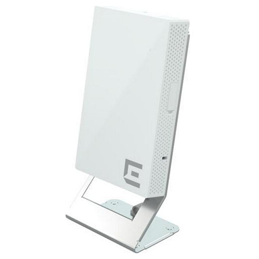
The ACC-BKT-AX-WP-DSKSTD accessory, also called the desk stand is used to install the access point to a desk. The desk stand accessory bag contains the following items:
One ACC-BKT-AX-WP-DSKSTD accessory
One flat head T8 security torx M2.5×6.5 mm long locking screw
Two Phillips flat head M3.5×12 mm long self-tapping wood screws
*Product Does not Include Access Point; Images for illustrative Purposes Only
Before you begin
The following hardware is required to install an indoor access point on a junction box (box):
An indoor access point
ACC-BKT-AX-JB accessory
About this task
The ACC-BKT-AX-JB accessory is used when you need to install the access point on an indoor junction box. The ACC-BKT-AX-JB access has two parts:
A metal part that attaches to the junction box (also called the sheet-metal junction box hole plate)
A plastic part that attaches to the metal part and the access point (also called the plastic twist plate)
Procedure
Remove the screws holding the junction box cover plate.
Remove the LAN cable from the cover plate.
Bring the LAN cable through the center hole of the metal bracket part.
*The LAN wire must be in-between the metal part and the plastic part during installation.
Place the ACC-BKT-AX-JB accessory metal part, with the bracket holes against the cover plate of the box.
Using the screws removed from the cover plate, find the bracket holes that align with the junction box screw holes.
*Important: The textf ro the holes must be normally readable
Using the cover plate screws, attach the metal bracket part to the junction box.
Place the plastic part on the metal part, rotate it ¼th to 1/3rd turn clockwise until you hear it click in place as the lock is set.
*Important: When installed correctly on a wall, the side arrows on the plastic part must be pointing up.
There is a metal pull ring in the metal part that is used to unlock and remove the plastic part.
To unlock the plastic part, pull out the pin's ring and turn the plastic part 1/3rd turn counter-clockwise and lift it apart.
Callout
Description
1
Sheet-metal junction box hole metal part
2
Plastic twist plate part
3
Pull ring with 10 mm diameter ring for unlocking the plastic part
Align the red dot on the back of the access point against the red dot on the plastic part.
Push the access point onto the plastic part and turn it clockwise until you hear it lock in place.
Insert the RJ45 cable connector to the Ethernet connector on the access point.
All indoor access point can use a flat Ethernet cable and cap, if desired
The Extreme Networks ACC-BKT-AX-ADAPT-012 mounting bracket adaptor provides a flexible solution for installing Extreme Networks wireless access points using existing third-party mounting hardware. Designed to work with Cisco AIR-AP-BRACKET-1 and AIR-AP-BRACKET-2, this adaptor bracket helps organisations reuse installed mounts while transitioning to Extreme Networks access points.
Key Features of Extreme Networks ACC-BKT-AX-ADAPT-012 Mounting Bracket Adaptor
Adaptor mounting bracket for Extreme Networks wireless access points
Compatible with third-party AIR-AP-BRACKET-1 and AIR-AP-BRACKET-2 mounts
Enables reuse of existing mounting infrastructure
Supports faster and more cost-effective AP deployments
Designed for secure and reliable access point installation
Reuse Existing Third-Party Mounting Hardware
The ACC-BKT-AX-ADAPT-012 adaptor allows Extreme Networks access points to be mounted using existing AIR-AP-BRACKET-1 and AIR-AP-BRACKET-2 installations. This reduces the need for new brackets and minimises disruption during network upgrades.
Ideal for Network Refresh Projects
When migrating from legacy or third-party wireless solutions, this adaptor bracket simplifies the transition. It enables organisations to deploy Extreme Networks access points without removing or replacing previously installed ceiling or wall mounts.
Secure and Stable Access Point Mounting
Built to ensure proper alignment and secure attachment, the adaptor bracket provides a stable mounting platform for supported Extreme Networks access points, helping maintain consistent placement and reliable wireless coverage.
Cost-Effective Installation Solution
By reusing existing mounting brackets, the ACC-BKT-AX-ADAPT-012 helps reduce installation time, labour costs, and additional hardware expenses, making it a practical choice for large-scale wireless deployments.
Designed for Professional Indoor Environments
This mounting adaptor is well suited to enterprise, education, retail, and commercial environments where clean installations, minimal downtime, and efficient hardware reuse are important considerations.

About this task
Attach the 37201 bracket to the wall before installing the WNGADAPT adapter. The 37201 main mounting bracket ships with the following items:
One 37201 main mounting bracket
Two Philips pan-head screws
Two screw-in anchors
*For concrete wall installations, you must provide screws and screw-in anchors.
Use the metal mounting bracket as a template and mark and drill two mounting holes.
*The four bracket feet and the engraved bracket arrows must be pointing up.
Attach the screw-in anchors to the mounting holes.
*Plastic screws and screw-in anchors are for drywall and metal screws and screw-in anchors are for drywall or wood wall installations.
For concrete wall installations, use a masonry anchor which slips into a drilled hole and expands as the bolt is tightened. Masonry anchors are not provided with the #37201 bracket.
Place the metal bracket over the mounting holes and run the LAN cable through the large center hole on the metal mounting bracket.
Attach the bracket using two pan-head screws for drywall, wood wall, or metal installations.
*Masonry anchors have integral threaded studs. If you are attaching the 37201 bracket to a concrete wall, then the anchor studs must protrude through the holes where a hex nut is tightened.
The WNGADAPT plate ships with two parts:
One WNGADAPT circular plastic twist part
One WNGADAPT metal plate
Procedure
With the WNGADAPT metal plate engraved arrows pointing up, place the WNGADAPT metal plate over the 37201 metal mounting bracket.
Run the LAN cable through the large center opening on the WNGADAPT plate.
Push the WNGADAPT metal plate down on to the 37201 bracket until the metal plate clicks in place.
Line the plastic twist part embossed dot against the red dot on the WNGADAPT metal plate.
*Bring the LAN cable up between the WNGADAPT metal plate and the plastic twist part.
Rotate the twist part clockwise quarter of a turn until the locking pin on the WNGADAPT metal plate clicks into place.
Line up the red dot on the rear of the access point against the red dot on the plastic twist part.
Ensure that the access point center recess area aligns onto the plastic twist center post.
Rotate the access point 1/6 of a turn clockwise until it clicks into place.
Insert the LAN cable into the RJ45 connector on top of the access point.
If there is a LAN cable PoE, the access point starts a boot cycle.
*If desired, use an in-line coupler, flat cable, and a cosmetic cap to attach the RJ45 cable onto the indoor access points.
About this task
The AP305C/CX access point can be mounted on a 15/16 in. wide ceiling rail using the ACC-BKT-TB-NF adapter, when the
ceiling tile protrudes below the T-bar. The AP305C/CX access point comes with in-built clips in the back of the access
point that attach directly on to the -NF adapter, eliminating the need for the -TB accessory.
Procedure
Remove the ceiling tiles.
Using the adapter guide on the top half of the ACC-BKT-TB-NF adapter, align and attach the -NF on to the ceiling
rail.
Callout
Description
1
Adapter guide for ceiling rail attachment
2
Adapter end
3
Indent for - NF second part attachment
4
Adapter tabs
Slide the other part of the -NF adapter onto the half attached to the ceiling rail.
*When the adapter parts are attached properly, the adapter ends will line up after the two halves have
snapped together.
Align the built-in clips on the AP305C/CX access point against the -NF adapter end.
Rotate the access point clockwise and attach it to the -NF adapter until it clicks into place.
Plug the RJ45 connector plug into ETH or ETH0, RJ45 connector receptacle on the access point.
Attach the Ethernet port cap to the access point Ethernet port.
Place the cable cover over the Ethernet cable.
Replace the ceiling tiles.


