


| Product Code: | |
| Options: | |
| Qty: | |
| Unit Price: | £ |
| Part No: | JNEX2300-C-RMK |
| Manufacturer No: | EX2300-C-RMK |
| Delivery: | In Stock: 5-7 Days |


 |
EX2300-C-RMK Rack-mount Kit
1. Remove the switch from the shipping carton
2. Place the switch on a flat, stable surface
3. Align the mounting brackets along the front or rear of the side panels of the switch chassis depending on how you want to mount the switch.
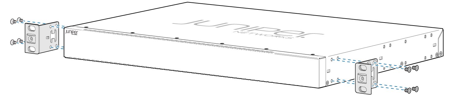
4. Align the bottom holes in the mounting brackets with the holes on the side panels of the switch chassis.
5. Insert the mounting screws into the aligned holes. Tighten the screws.
6. Ensure that the other holes in the mounting brackets are aligned with the holes in the side panels. Insert a screw in each hole and tighten the screws.
7. Have one person grasp both sides of the switch, lift the switch, and position it in the rack, aligning the mounting bracket holes with the threaded holes in the rack rail. Align the bottom hole in each mounting bracket with a hole in each rack rail, making sure the chassis is level.
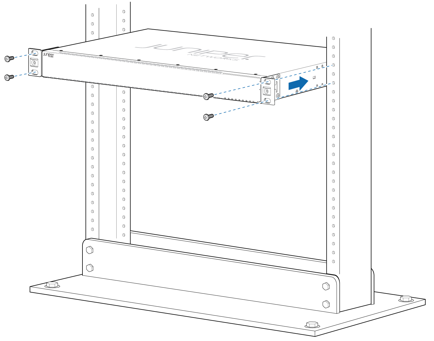
8. Have a second person secure the switch to the rack by using the appropriate screws. Tighten the screws.
9. Ensure that the switch chassis is level by verifying that all screws on one side of the rack are aligned with the screws on the other side.
1. Remove the switch from the shipping carton
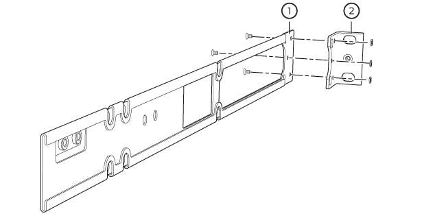
2. Attach the front-mounting brackets (either the flush or the 2-in.-recess brackets) to the side mounting-rails by using 6 Phillips 4-40 flat-head mounting screws.
3. Place the switch on a flat, stable surface.
4. Align the side mounting-rails along the side panels of the switch chassis. Align the two holes in the rear of the side mounting-rails with the two holes on the rear of the side panel.
5. Insert the Phillips 4x6-mm flat-head mounting screws into the two aligned holes and tighten the screws. Ensure that the two holes in the rear of the side mounting-rails are aligned with the remaining two holes in the side panel.
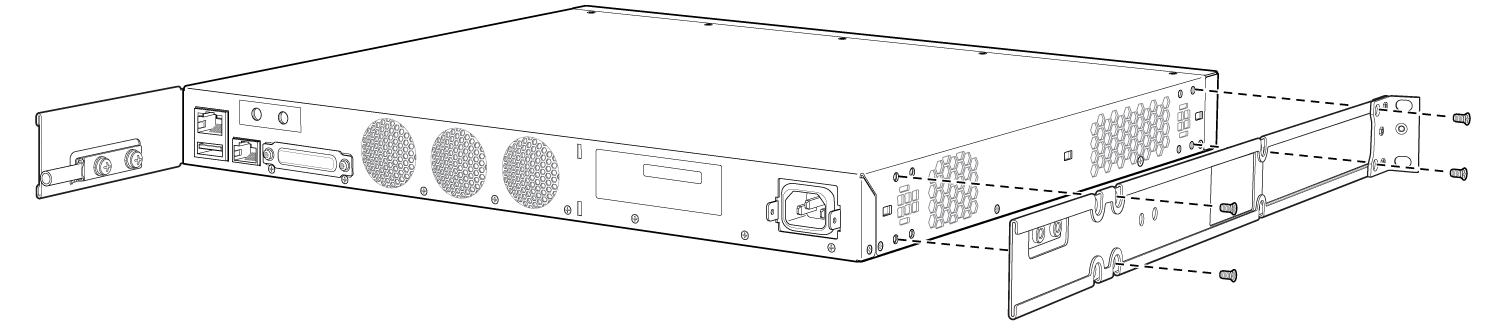
6. Insert the Phillips 4x6-mm flat-head mounting screws into the remaining two holes in the side mounting-rails and tighten the screws.
7. Have one person grasp both sides of the switch, lift the switch, and position it in the rack, aligning the side mounting-rail holes with the threaded holes in the front post of the rack. Align the bottom hole in both the front-mounting brackets with a hole in each rack rail, making sure that the chassis is level.
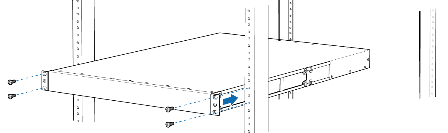
8. Have a second person secure the front of the switch to the rack by using the appropriate screws for your rack.
9. Slide the rear mounting-blades into the side mounting-rails.
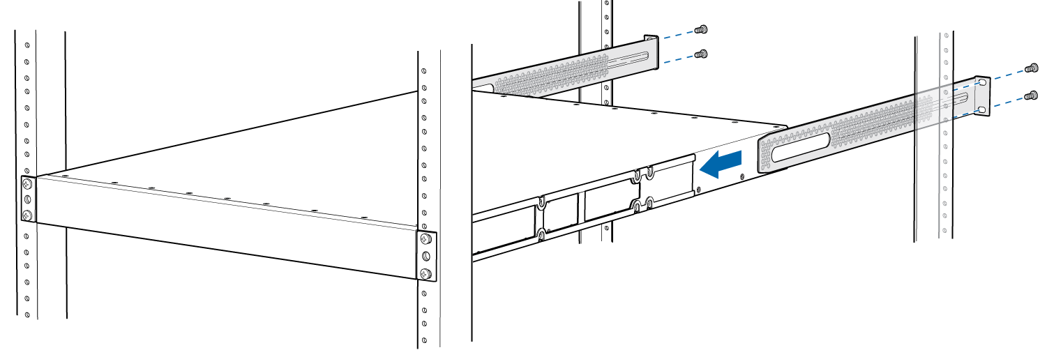
10. Attach the rear mounting-blades to the rear post by using the appropriate screws for your rack. Tighten the screws.
11. Ensure that the switch chassis is level by verifying that all the screws on the front of the rack are aligned with the screws at the back of the rack.
EX2300-C-RMK Rack-mount Kit
1. Remove the switch from the shipping carton
2. Place the switch on a flat, stable surface
3. Align the mounting brackets along the front or rear of the side panels of the switch chassis depending on how you want to mount the switch.
4. Align the bottom holes in the mounting brackets with the holes on the side panels of the switch chassis.
5. Insert the mounting screws into the aligned holes. Tighten the screws.
6. Ensure that the other holes in the mounting brackets are aligned with the holes in the side panels. Insert a screw in each hole and tighten the screws.
7. Have one person grasp both sides of the switch, lift the switch, and position it in the rack, aligning the mounting bracket holes with the threaded holes in the rack rail. Align the bottom hole in each mounting bracket with a hole in each rack rail, making sure the chassis is level.
8. Have a second person secure the switch to the rack by using the appropriate screws. Tighten the screws.
9. Ensure that the switch chassis is level by verifying that all screws on one side of the rack are aligned with the screws on the other side.
1. Remove the switch from the shipping carton
2. Attach the front-mounting brackets (either the flush or the 2-in.-recess brackets) to the side mounting-rails by using 6 Phillips 4-40 flat-head mounting screws.
3. Place the switch on a flat, stable surface.
4. Align the side mounting-rails along the side panels of the switch chassis. Align the two holes in the rear of the side mounting-rails with the two holes on the rear of the side panel.
5. Insert the Phillips 4x6-mm flat-head mounting screws into the two aligned holes and tighten the screws. Ensure that the two holes in the rear of the side mounting-rails are aligned with the remaining two holes in the side panel.
6. Insert the Phillips 4x6-mm flat-head mounting screws into the remaining two holes in the side mounting-rails and tighten the screws.
7. Have one person grasp both sides of the switch, lift the switch, and position it in the rack, aligning the side mounting-rail holes with the threaded holes in the front post of the rack. Align the bottom hole in both the front-mounting brackets with a hole in each rack rail, making sure that the chassis is level.
8. Have a second person secure the front of the switch to the rack by using the appropriate screws for your rack.
9. Slide the rear mounting-blades into the side mounting-rails.
10. Attach the rear mounting-blades to the rear post by using the appropriate screws for your rack. Tighten the screws.
11. Ensure that the switch chassis is level by verifying that all the screws on the front of the rack are aligned with the screws at the back of the rack.
Product data is provided by Icecat, we do not warrant the accuracy of the material above.