


| Product Code: | |
| Options: | |
| Qty: | |
| Unit Price: | £ |
| Part No: | JNEX-UM-4SFPP-MR |
| Manufacturer No: | EX-UM-4SFPP-MR |
| Delivery: | In Stock: 5-7 Days |


 |
EX4300MP 4-port Uplink Module
1GbE/10GbE SFP+
4-port 1-Gigabit Ethernet / 10-Gigabit Ethernet SFP+ uplink module
You can install four SFP transceivers, four SFP+ transceivers, or a combination of SFP and SFP+ transceivers in the four ports of this uplink module.
1. Wrap and fasten one end of an ESD wrist strap around your bare wrist, and connect the other end of the strap to the ESD point on the switch. If a grounding strap is not available, hold the uplink module in its antistatic bag in one hand and touch the exposed, bare metal of the switch with the other hand to ground yourself and the component.
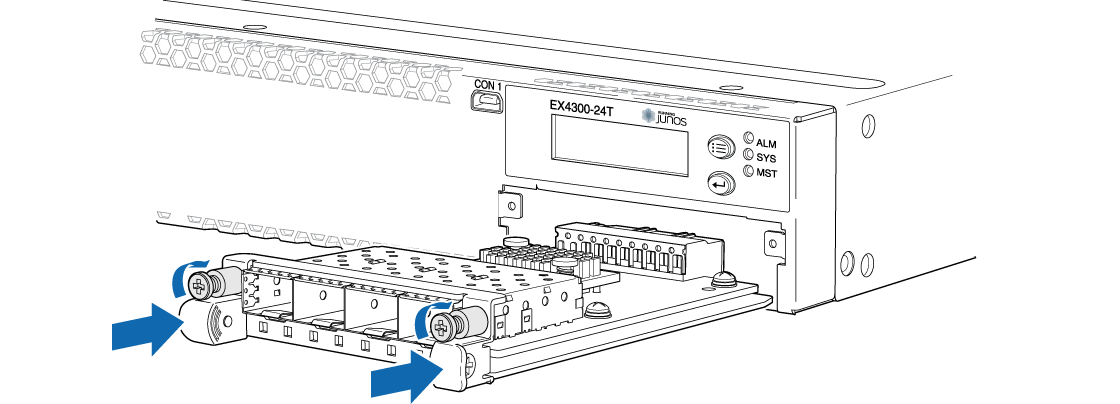
2. If the uplink module slot has a cover panel on it, loosen both captive screws on the faceplate of the uplink module by using your fingers. If you are unable to unscrew the captive screws by using your fingers, use the screwdriver. Hold both the captive screws and gently pull it outward to remove the cover panel, and save it for later use.
3. Taking care not to touch module components, pins, leads, or solder connections, remove the uplink module from its bag.
4. Using both hands, place the module in the empty slot and slide it in gently until it is fully seated.
5. Tighten both the captive screws by using your fingers or the screwdriver.
EX4300MP 4-port Uplink Module
1GbE/10GbE SFP+
4-port 1-Gigabit Ethernet / 10-Gigabit Ethernet SFP+ uplink module
You can install four SFP transceivers, four SFP+ transceivers, or a combination of SFP and SFP+ transceivers in the four ports of this uplink module.
1. Wrap and fasten one end of an ESD wrist strap around your bare wrist, and connect the other end of the strap to the ESD point on the switch. If a grounding strap is not available, hold the uplink module in its antistatic bag in one hand and touch the exposed, bare metal of the switch with the other hand to ground yourself and the component.
2. If the uplink module slot has a cover panel on it, loosen both captive screws on the faceplate of the uplink module by using your fingers. If you are unable to unscrew the captive screws by using your fingers, use the screwdriver. Hold both the captive screws and gently pull it outward to remove the cover panel, and save it for later use.
3. Taking care not to touch module components, pins, leads, or solder connections, remove the uplink module from its bag.
4. Using both hands, place the module in the empty slot and slide it in gently until it is fully seated.
5. Tighten both the captive screws by using your fingers or the screwdriver.
Product data is provided by Icecat, we do not warrant the accuracy of the material above.