Back-UPS ES 400/550/700
Stage 1: Connect Battery
For safety, the Back-UPS ES is shipped with one battery wire disconnected. The Back-UPS ES will not operate until the wire is connected to the touch.
NOTE: Small sparks may occur during battery connection but this is normal.

- TURN the Back-UPS ES over and slide the battery compartment cover off of the battery housing.
- LIFT the battery out of the compartment and connect the black wire to the negative (-) battery terminal. Ensure the batteries are installed as shown above.
- SLIDE the battery compartment cover back onto the battery housing.
Stage 2: Connect Equipment
![]()
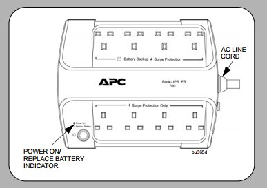
These outlets are powered whenever the Back-UPS ES is switched ON. During a power outage or other AC problems (brownouts, over-voltages), these outlets will be powered for a limited time by the Back-UPS ES. Plug your computer, monitor, and two other data-sensitive devices (external disk or tape drive) into these outlets.
Surge Protection Only
The outlets provide full-time protection from surges even if the Back-UPS ES is switched OFF. Plug your printer, fax machine, scanner, or other peripherals that do not need battery power into these outlets.
Place the Back-UPS ES to avoid:
- Direct sunlight
- Excessive heat
- Excessive humidity or contact with fluids
Plug the Back-UPS ES power cord directly into a wall outlet; not a surge protector or power strip. The wall outlet should be located near the equipment and be easily accessible.
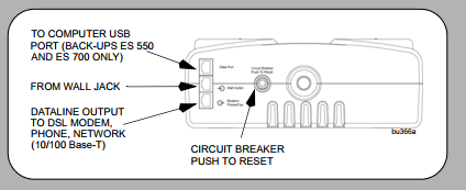
Connect Modem / Phone / DSL / Fax / 10/100 Base- T/HPNA to Surge Protection.
The Back-UPS protects a single line (2-wire) phone (including Digital Subscriber line – DSL), Home Phoneline Networking Association (HPNA) type equipment, modem, 10/100 Base-T Ethernet, or fax machines from surges when connected through the UPS as shown in the drawing below.
Note: Telephone Cable OR Network Cable should be connected to Surge Protection ports. Do not connect the UPS surge protection ports to both Telephone and Network System cables at the same time.
Connect Computer Cable (This is applicable for 550/700 only)
The supplied cable and software provide automatic file saving and shutdown of the operating system in the case of a sustained power outage.
Connect the cable to the Data Port of the Back-UPS ES. Connect the other end of the cable to the USB port on your computer. The software will automatically find the USB Port of your computer
Stage 3: Power On and Install Software
Press the ON/OFF switch to power the unit ON.
A single short beep and the green “Power On” indicator confirms that Back-UPS ES is on and ready to provide protection. The Back-UPS ES should charge for at least 16 hours to ensure sufficient run-time. The unit is being charged whenever it is connected to AC power, whether the unit is turned ON or OFF. Install the PowerChute™ Personal Edition software (This is applicable for 550/700 only).
Place the PowerChute Personal Edition CDROM into your computer and follow the installation instructions on the screen.
Status Indicators
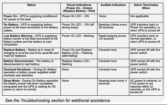
The Back-UPS ES indicates operating status using a combination of visual and audible indicators. Use the following table to identify the status of the Back-UPS ES:
Troubleshooting
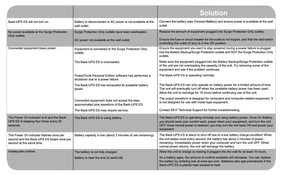
Use the table below to solve minor Back-UPS ES installation or operation problems. Consult Schneider Electric IT (SEIT) Online Technical Support or call SEIT Technical Support for assistance with problems that cannot be resolved using the table below:
Order Replacement Battery
Replace with an APC by Schneider Electric qualified battery. For Back-UPS ES 400, order APCRBC106 as directed by SEIT Technical Support. For Back-UPS ES 550, order RBC2. For Back-UPS ES 700, order RBC17.
Warranty
The standard warranty is three years from the date of purchase. Schneider Electric IT’s (SEIT) standard procedure is to replace the original unit with a factory reconditioned unit. Customers who must have the original unit back due to the assignment of asset tags and set depreciation schedules must declare such a need at first contact with an SEIT Technical Support representative.
SEIT will ship the replacement unit once the defective unit has been received by the repair department, or cross-ship upon the receipt of a valid credit card number. The customer pays for shipping the unit to SEIT. SEIT pays ground freight transportation costs to ship the replacement unit to the customer
Service
If the unit requires service, do not return it to the dealer. Follow these steps:
1. Review the Troubleshooting section of the manual to eliminate common problems.
2. If the problem persists, contact Schneider Electric IT (SEIT) Customer Support through the APC by Schneider Electric Web site, www.apc.com.
a. Note the model number and serial number and the date of purchase. The model and serial numbers are located on the rear panel of the unit and are available through the LCD display on select models.
b. Call SEIT Customer Support and a technician will attempt to solve the problem over the phone. If this is not possible, the technician will issue a Returned Material Authorization Number (RMA#).
c. If the unit is under warranty, the repairs are free.
d. Service procedures and returns may vary internationally. Refer to the APC by Schneider Electric Web site for country-specific instructions.
3. Pack the unit in the original packaging whenever possible to avoid damage in transit. Never use foam beads for packaging. Damage sustained in transit is not covered under warranty.
4. Always DISCONNECT THE UPS BATTERIES before shipping. The United States Department of Transportation (DOT), and the International Air Transport Association (IATA) regulations require that UPS batteries be disconnected before shipping. The internal batteries may remain in the UPS.
5. Write the RMA# provided by Customer Support on the outside of the package.
6. Return the unit by an insured, pre-paid carrier to the address provided by Customer Support.
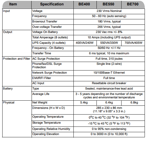
Specifications
Wall Mount of UPS
The UPS can be mounted vertically or horizontally to a wall surface. Use the template below to position the mounting fasteners (not supplied). Wall mount the UPS as follows;
1. Hold this page against the wall in the desired mounting location.
2. Use thumbtacks or tape to hold this page in place against the wall. Use a sharp nail or pin to puncture the centre of each template circle to mark the wall.
3. Install the mounting fasteners at the marked locations. Leave the head of both fasteners 8mm (5/16) out from the face of the wall. The fasteners must be able to support 6.8 Kg.
4. Mount the UPS by positioning the key-hole slots over the heads of the mounting fasteners. For vertical mounting, slide the UPS down into place. For horizontal mounting, turn it slightly counter clockwise until it is securely in place.

