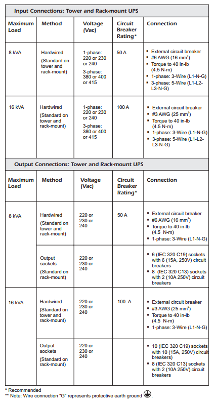
For use with Symmetra LX UPS Models:
- 220/230/240 V, 4 8 kVA
- 220/230/240 V, 4 16 kVA
Important Safety and Installation Instructions
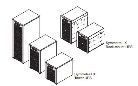
This manual provides instructions on the wiring and connections for the
APC Symmetra LX tower and rack-mount UPS.
All electrical power and power control wiring must be installed by a qualified
electrician and comply with local and national regulations.
See and retain the product documentation shipped with your system for
other important installation, operation, and maintenance instructions.
Illustrations are representative. Your Symmetra LX configuration, including
components and optional APC equipment may be different from the models
shown in this guide.
Electrical Installation

Read, understand and follow ALL safety instructions contained in the Symmetra LX Safety Instructions and General Information Guide. Failure to follow safety instructions and warnings could result in equipment damage, serious injury or death.
1. Complete Pre-installation Checklist
Before beginning the electrical installation, perform the following procedures.
1.1 Check that the circuit breaker to be used to power the UPS is in the
OFF position.
1.2 Check that the input circuit breaker A on the UPS is in the OFF
position.
2. Hardwire the UPS
- Refer to local and national codes. Many locations require hardwiring
by a licensed electrician. - Strain relief is required for all hardwiring.
- All openings in the hardwire assembly must be covered. Failure to
do so may result in personal injury or equipment damage.
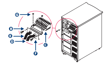
![]()
1.1 Remove screws B and slide out the hardwire assembly C.
2.2 Attach an input conduit D and if required, an output conduit E .
Larger holes can be punched if necessary.
Detach the strain relief panel F using nuts G for easier access.
Hardwire the UPS (continued)
2.3 Attach an input cable H and an output cable (if required) I, to
the terminal block.
- Pull the wires through the conduit into the hardwire assembly.
- Connect to the terminal block as indicated on the label,
using a torque of 40 in-lb (4.5 N-m).
For 1-phase wiring, use L1, N, and G only. For 3-phase wiring,
use L1, L2, L3, N, and G only.
- Cover the unused holes in the strain relief panel.
2.4 Inspect cable connections to ensure proper installation.
2.5 Reattach the strain relief panel with nuts L.
2.6 Reinstall the hardwire assembly with provided screws M.
2.7 Test the wiring.
- Turn on the utility power, the input circuit breaker, and the
system enable switch. If the Vin value on the display does
not match your branch voltage, check the input wiring. - Check the output wiring by turning on the maintenance bypass
switch.
2.8 Turn OFF the input circuit breaker and maintenance bypass
switch.
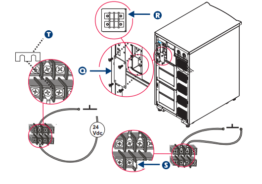
3. Connect Remote Emergency Power Off (REPO)
Circuit, If Required
- In many locations, the Remote Emergency Power Off
(REPO) switch must be installed by a licensed electrician.
Refer to local and national codes. - See the Symmetra LX Safety and General Information Guide for REPO requirements and detailed safety instructions.
3.1 Remove the access panel Q to connect the circuits R.
3.2 If your installation will use an external switch contact, connect
the REPO switch with the pre-installed jumper S, as shown.
3.3 If your installation will use a switch contact and a 24 V power supply
external to the UPS, remove the jumper T and connect the REPO
switch, as shown.
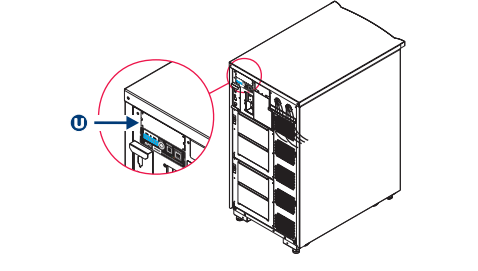
4. Install Accessory Card, If Applicable
If your configuration includes an additional management accessory
card, install in the empty slot U on the rear of the UPS. See the
accompanying documentation for installation instructions.
5. Install PDU Panel(s) and Connect Loads to the UPS,
If Applicable
Your configuration may include optional PDU panels. Refer to the PDU
installation guide.
Loads can be connected directly to the UPS using the output
sockets on the PDU panel. Ensure that the total load being plugged
into a PDU panel DOES NOT EXCEED the branch circuit breaker
rating on the PDU panel.
All UPS configurations can be wired 3-phase in / 1-phase out, or
1-phase in / 1-phase out.